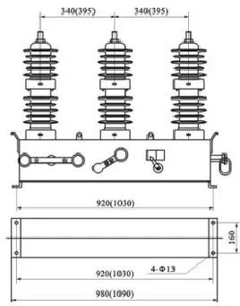
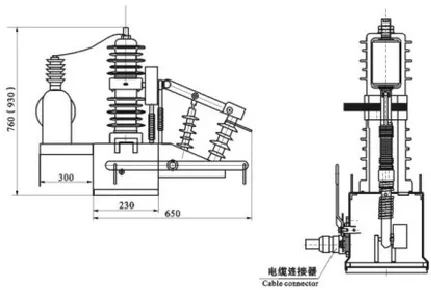
ZW32 Primary-Secondary Deeply Integrated Complete Set Pole-Mounted Circuit Breaker (Pole Type)
The 12 kV outdoor pole-mounted vacuum circuit breaker adopts a three-phase pole-mounted structure with longitudinal magnetic field vacuum arc extinguishing technology, ensuring stable and reliable interruption performance. It uses silicone rubber/epoxy resin solid insulation, posing no risk of combustion or explosion. The breaker is maintenance-free, lightweight, easy to install, and has a long service life (mechanical life up to 10,000 operations). The newly designed spring operating mechanism employs a linear transmission method, which is convenient and reliable, effectively avoiding the design flaws of traditional spring mechanisms such as susceptibility to sticking and rusting, thereby significantly improving mechanism reliability.
The primary-secondary integrated complete set of pole-mounted vacuum circuit breaker is a newly developed product conforming to smart circuit breaker standards, and its switch configuration fully meets the requirements of the State Grid's primary-secondary integration. The switch features a compact structure and rational layout, with four-remote (telemetering, telesignaling, telecontrol, television) functionality, and all indicators comply with the State Grid's primary-secondary integration requirements. The protection CT, zero-sequence CT, and zero-sequence voltage sensor, uniformly developed by the company, offer wide measurement range, high measurement accuracy, and high reliability, facilitating accurate determination of various feeder line faults, including broken line faults.
The breaker enclosure is made of 3mm thick 304 stainless steel, with a protection rating of not less than IP54. A clearly visible open/close position indicator, easily observable from ground level, is provided on the enclosure. The indicator is reliably connected to the operating mechanism, ensuring dependable indication. A rust-proof grounding screw of 12 mm diameter shall be provided, and the grounding point shall be marked with the grounding symbol. The enclosure surface is designed with protrusions to prevent water accumulation. The enclosure is equipped with handling grips to avoid pulling on the outlet bushings. Lifting lugs are provided to keep the switch device level during hoisting, and the lifting chains shall have no frictional contact with any components to avoid scratching the surface coating during lifting. The nameplate is made of 304 stainless steel, capable of withstanding weather conditions and remaining clearly legible throughout service life, and the nameplate content complies with relevant standard requirements.
The switch is configured with three current transformers for phases A, B, and C, with a transformation ratio selectable from 600:1A to 2500:1A, class 10P10.
The switch is configured with three voltage sensors on the load side for phases R, S, and T, with a transformation ratio selectable from phase voltage/0.4 to 7V, and the accuracy is stably maintained at class 1.0%.
The switch is configured with individual zero-sequence current transformers for phases A, B, and C, with a transformation ratio of 1000:1A (optional), and an accuracy class of 0.5.
To prevent overcurrent of the current measuring device and CT open circuit, the product is equipped with a protection device.
Adopts three-remote (telemetering, telesignaling, telecontrol) design, with a built-in high-precision energy metering module to meet high-voltage line loss calculation requirements.
Allows flexible configuration of operating parameters and control logic based on actual operating conditions, enabling single-phase grounding and phase-to-phase short-circuit fault handling. It can directly trip to clear faults and features an automatic reclosing function with adjustable reclosing times and intervals.
Equipped with transient waveform recording function, capable of recording single-phase grounding fault waveforms and uploading the data to the distribution automation master station, complying with relevant communication protocols.
Shall be equipped with inrush current protection function.
Features adaptive integrated local feeder automation function, independent of the master station and communication. Through control logics such as short-circuit/grounding fault detection technology, no-voltage tripping, and fault-path adaptive delayed incoming closing, it adapts to multi-branch, multi-tie distribution network architectures, enabling local fault line selection, section location, and isolation for single-phase grounding faults.
Cooperates with the first closing of the substation outlet circuit breaker to achieve section location of permanent short-circuit faults and power restoration for transient faults.
Cooperates with the second closing of the substation outlet circuit breaker to achieve local automatic isolation of permanent faults and power restoration in the upstream area of the fault.
◆ Ambient air temperature: -40℃ to 40℃;
◆ Altitude: not exceeding 3000m;
◆ The ambient air may be contaminated by dust, smoke, corrosive gases, steam or salt spray; Pollution class: Class IV;
◆ Wind speed not exceeding 34m/s (equivalent to 700Pa on cylindrical surface);
◆ Vibration or ground movement from external sources outside the switchgear and controlgear is negligible;
◆ The amplitude of electromagnetic interference induced in the secondary system does not exceed 1.10kV.
GB 1984-2014 "High-voltage alternating-current circuit-breakers"
GB/T 11022-2011 "Common specifications for high-voltage switchgear and controlgear standards"
GB 20840.1-2010 "Instrument transformers – Part 1: General requirements"
GB 20840.2-2014 "Instrument transformers – Part 2: Additional requirements for current transformers"
|
Serial Number |
Name |
Unit |
Parameter |
|
Circuit Breaker Body |
|||
|
1 |
Arc Extinguishing Method |
|
Vacuum |
|
2 |
Rated Voltage |
kV |
12 |
|
3 |
Rated Current |
A |
630 |
|
4 |
Rated Frequency |
Hz |
50 |
|
5 |
Rated Short-Circuit Breaking Current Value |
kA |
20 |
|
6 |
Rated Short-Circuit Making Current (Peak) |
kA |
50 |
|
7 |
Rated Short-Time Withstand Current (4s) |
kA |
20 |
|
8 |
Rated Peak Withstand Current |
kA |
50 |
|
9 |
Rated Short-Circuit Current Breaking Operations |
|
30 |
|
10 |
Closing Speed |
m/s |
0.8±0.2 |
|
11 |
Opening Speed |
m/s |
1.2±0.2 |
|
12 |
Type of Operating Mechanism |
|
Spring |
|
13 |
Operating Mode |
|
Electric, Manual |
|
14 |
Motor Voltage |
v |
DC24 |
|
15 |
Closing and Opening Voltage |
v |
DC24 |
|
16 |
Mechanical Life |
|
10000 |
|
17 |
Weight |
kg |
<130 |
|
18 |
Enclosure Material |
|
304 stainless steel, not less than 2mm |
Electronic current transformer:
|
1 |
Rated Current Ratio |
(1) Phase current: 600A/1V (2) Zero-sequence current: 20A/0.2V |
|
2 |
Accuracy Class |
Phase: Protection Class 5P10, Measurement Class 0.5S |
|
3 |
Temperature Range |
Low-Power Electromagnetic Type |
|
4 |
Partial Discharge |
≥20kΩ |
|
5 |
Load Impedance |
-40℃~70℃ |
Electronic voltage transformer:
|
1 |
Rated Voltage Ratio |
(1)Phase Voltage:(10kV/√3)/3.25/√3(2) |
|
2 |
Accuracy Class |
(1) Phase voltage: Class 0.5 (2) Zero-sequence voltage: Class 3P |
|
3 |
Temperature Range |
-40℃~70℃ |
|
4 |
Partial Discharge |
≤20(1.1Um) |
|
5 |
Load Impedance |
≥2kΩ |
Electromagnetic current transformer:
|
1 |
Rated Current Ratio |
|
Phase Current: 600A/1A |
|
2 |
Accuracy Class |
Class |
Phase Current: Protection Class 5P10, Measurement Class 0.5 |
|
3 |
Capacity |
VA |
Phase CT: 1VA Zero-Sequence CT: 1VA |
|
4 |
Temperature Range |
℃ |
-40℃~70℃ |
Zero-sequence voltage transformer:
|
1 |
Turns Ratio |
|
(10kV/√3)/(6.5V/√3) |
|
2 |
Accuracy Class |
Class |
3P |
|
3 |
Partial Discharge |
pC |
≤20(1.2Um/√3) |
|
4 |
Insulation Resistance After Combination with Switch (Switch Phase to Ground) |
MΩ |
≥1000 |
|
5 |
Implementation Method |
|
Capacitive Voltage Divider |
Arc Extinguishing Principle:
The ZW32 permanent magnet vacuum circuit breaker adopts a vacuum interrupter, using vacuum as the arc extinguishing and insulating medium, with an extremely high degree of vacuum. When the moving and fixed contacts are opened under the action of the operating mechanism while energized, a vacuum arc is generated between the contacts. At the same time, due to the special contact structure, an appropriate longitudinal magnetic field is also generated in the contact gap, which promotes the vacuum arc to remain in a diffuse type and causes the arc to burn evenly across the contact surface, maintaining a low arc voltage. When the current naturally passes through zero, the residual ions, electrons, and metal vapor recombine or condense on the contact surface and the shield within a time frame on the order of microseconds. The dielectric insulation strength of the interrupter gap is quickly restored, thereby extinguishing the arc and achieving interruption. Due to the use of a longitudinal magnetic field to control the vacuum arc, the vacuum circuit breaker has a strong and stable current interruption capability.
Energy Storage:
The opening and closing energy of the ZW32 permanent magnet vacuum circuit breaker is stored in high-performance capacitors, which are installed inside the feeder terminal unit (FTU) enclosure. During opening and closing operations, energy is provided by the instantaneous discharge of the capacitors. The charging energy for the capacitors is supplied by the main power source or backup power source of the feeder terminal unit (FTU), with a charging time not exceeding 10 seconds, and a capacitor voltage error of ≤1V.
Closing Operation:
Press the close button locally on the device, or control the closing operation through the feeder terminal unit (FTU) to energize the closing coil of the operating mechanism, causing the iron core to drive the moving contact of the circuit breaker to close at the specified speed. When it is determined that the circuit breaker is in the closed position, the control circuit automatically disconnects the power supply to the closing coil. At this point, the iron core remains on the closing side due to the action of the permanent magnet. After the closing coil is de-energized, it not only overcomes the reaction force of the circuit breaker's contact springs but also provides a closing self-holding force, keeping the circuit breaker reliably in the closed position.
Opening Operation:
The feeder terminal unit (FTU) controls the opening operation, energizing the opening coil of the operating mechanism. While overcoming the self-holding force of the permanent magnet on the closing side, the opening spring pulls the iron core to drive the moving contact of the circuit breaker to open at the specified speed. When it is determined that the circuit breaker is in the open position, the control circuit automatically disconnects the power supply to the opening coil. At this point, the iron core remains on the opening side due to the tension of the opening spring, keeping the circuit breaker reliably in the open position.
Manual Emergency Opening Operation:
When the circuit breaker is in the closed position, use an insulated operating hook to catch the pull ring on the manual opening handle of the circuit breaker and pull it downward. The circuit breaker will then open, maintaining a certain opening speed to ensure reliable interruption of the rated load current.